

Spread-Spectrum
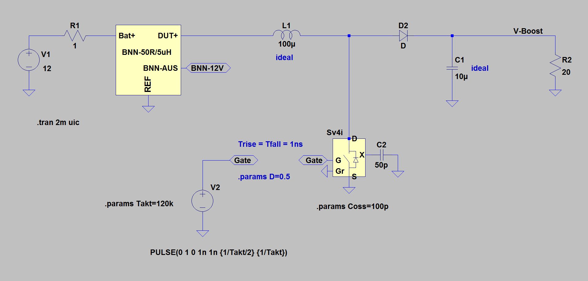
The picture shows a simplified booster circuit with fixed clocking. Simplified here means that parasitic elements in the coils and capacitors have been omitted, as well as any filter elements - on the one hand to make the circuit and the behavior as clear as possible, on the other hand, to obtain sufficiently large perturbations and to avoid problems with the dynamic range for the FFT. The fixed clock booster is the comparison reference for the spread spectrum modulator circuits.
Simplified booster circuit with fixed switching frequency
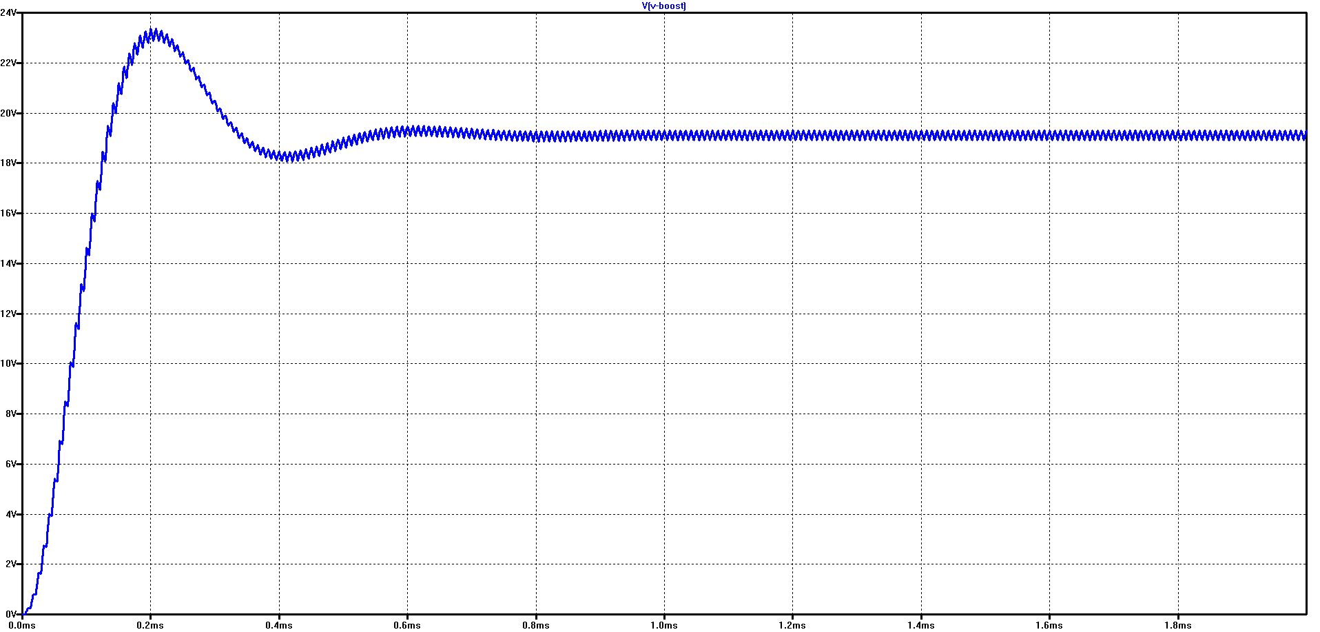
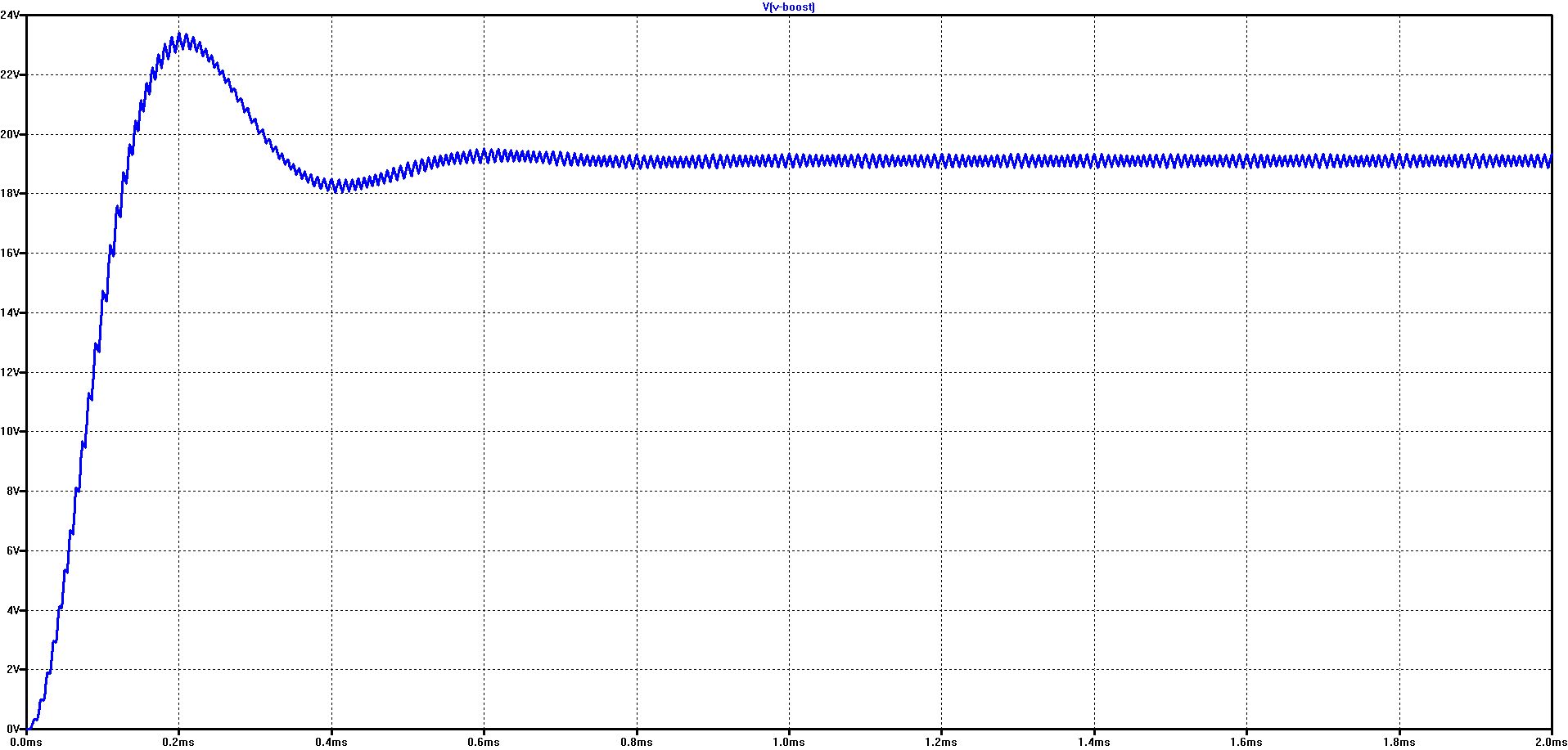
The diagram shows the ramp-up of the output voltage
Already after 1 ms, a stable, steady state is reached (because with R1 = 1 ohm a relatively high internal resistance was selected)
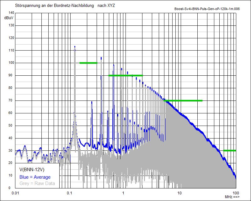
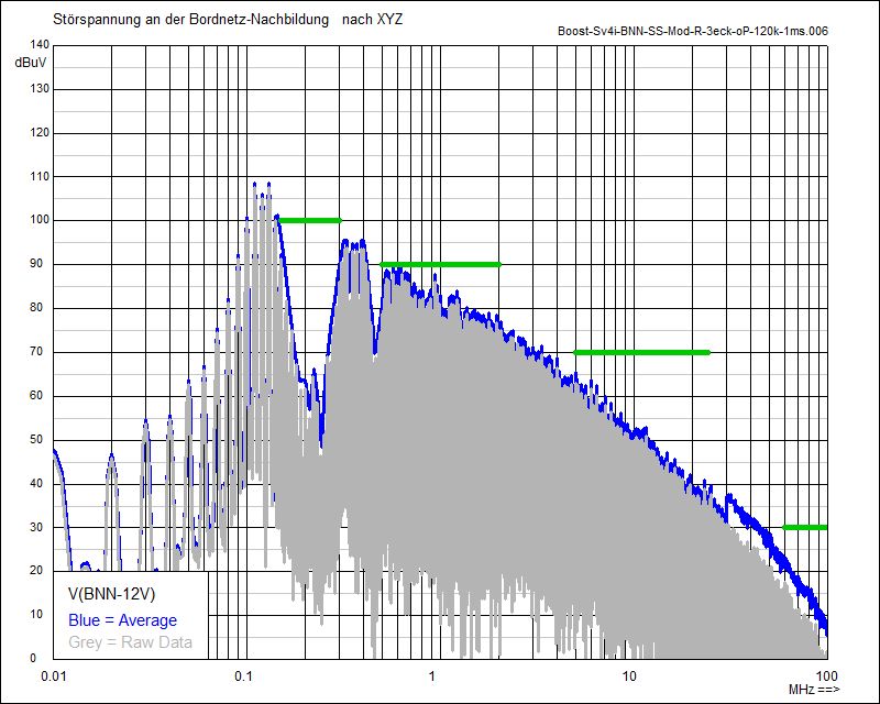
Spectrum of the booster circuit with fixed switching frequency (120 kHz)
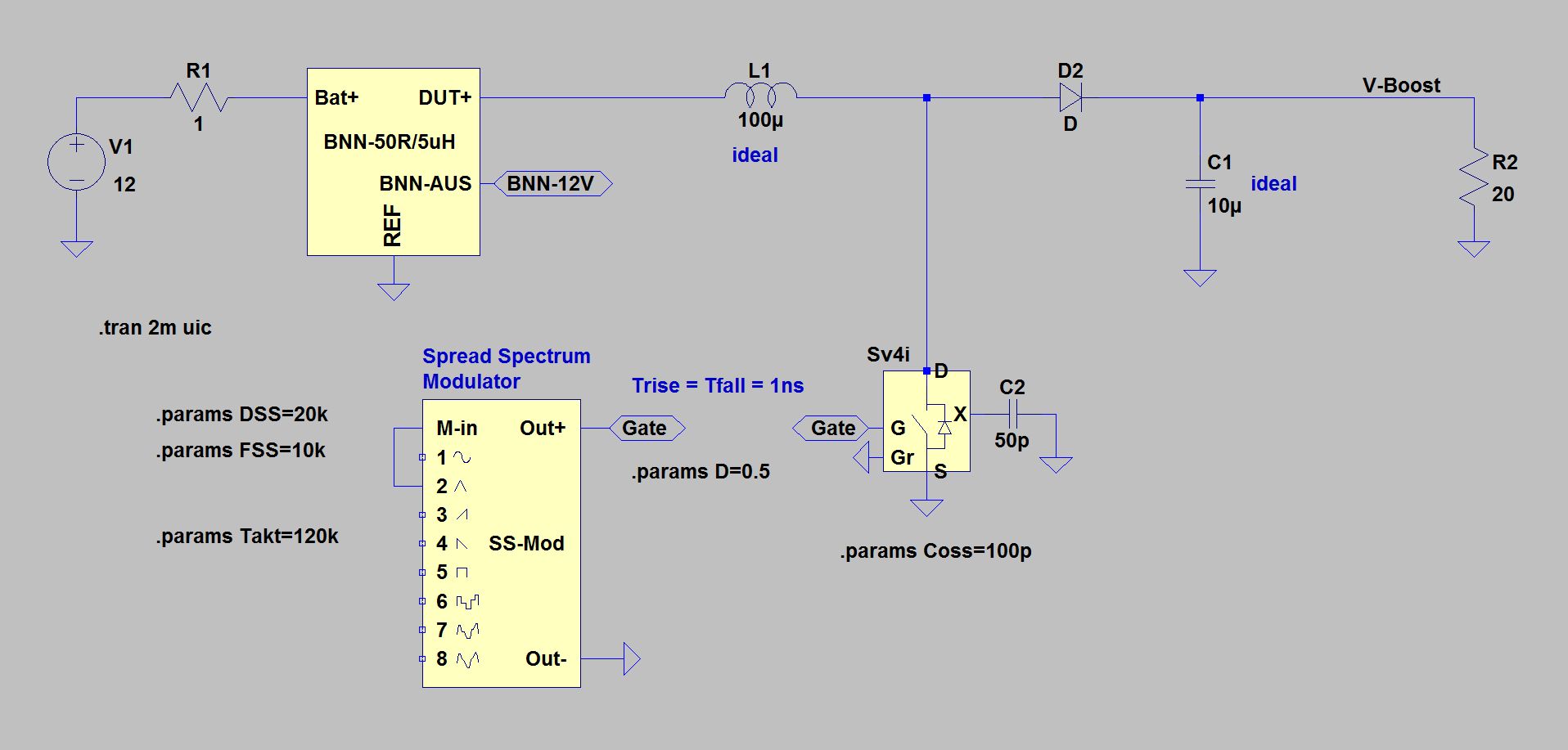
Booster circuit with Spread-Spectrum-Modulator
Different to the previous circuit, a Spread-Spectrum-Modulator is now used to control the booster switch. The modulator can vary the drive signal for the switch in the frequency domain according to different, selectable time courses. In this example, the frequency domain is modulated triangular.
Output voltage curve with Spread-Spectrum-Modulator with triangular modulation
The course shows no significant difference to the booster with a fixed clock
Spectrum with fixed switching frequency
Spectrum with Spread-Spectrum (Delta-Frequency = 20 kHz)
The effect of the Spread-Spectrum-Modulation is clearly visible compared to the unmodulated fixed clock circuit. The triangular modulation used in this example produces additional 10 kHz sidebands, while at the same time the original spectral lines of the fundamental frequency (120 kHz) and the harmonics decrease in level.
The reduction in the level is different over the frequency range: about 10 dB at the 3rd and 5th harmonic (360 and 600 kHz), but increasingly less with increasing frequency (almost no effect in the FM range) and little effect on the fundamental.
The exact effect of the Spread-Spectrum-Modulation depends on the type of modulation, the measuring bandwidth, the measuring time in the level calculation, the delta frequency and finally the respective design of the detector. The operation of peak, average and quasi-peak detectors is described e.g. described in CISPR 16-1-1. The bandwidth assessment used here uses an averaging algorithm with 200 Hz bandwidth below 150 kHz, 10 kHz bandwidth from 150 kHz to 30 MHz and 120 kHz bandwidth above 30 MHz.
Further information can be found in the chapters Spread-Spectrum-Modulation, Effect of Measuring Time and Delta-Frequency.
© Ingenieurbüro Lindenberger 8447